
Content
Your brackish water RO train is producing the permeate flow you need, but the feed pump is taking a growing share of the plant's electricity budget. The feed water is low in dissolved solids, around 1,200 ppm, yet the standard brackish water elements in the vessels demand 200 psi or more to hold their rated output. In this situation, a custom extreme low pressure RO membrane is usually the most direct fix.
An XLP element does the same desalting job at roughly half the feed pressure. Typical operation lands near 100 psi, stabilized salt rejection stays above 99 percent, and pump energy consumption drops by as much as 35 percent on low-TDS feed water. The savings are real, the retrofit is simple, and the technology has matured to the point where it belongs in any engineer's evaluation of new or existing RO capacity.
Extreme low pressure membranes sit at the lowest end of the reverse osmosis pressure spectrum. Ultra low pressure (ULP) elements operate around 120 to 150 psi. XLP elements go a step further and are designed for 80 to 100 psi, close to the practical lower limit where a polyamide RO membrane can still deliver stable rejection and economical permeate flow.
That low operating range comes with a small trade-off. XLP membranes are tuned for feed water with a TDS below roughly 2,000 ppm. In that range, stabilized rejection is typically 99.0 to 99.2 percent, slightly below the 99.5 percent of a standard brackish water membrane. For most industrial process water and groundwater applications, the permeate quality difference is negligible, while the energy difference is substantial.
The performance of an XLP membrane is determined in the manufacturing stage, not by simply lowering the pump pressure on a standard element. Three structural choices make the difference:
An XLP element is therefore not a weaker version of a brackish water element. It is a purpose-built component designed for a specific TDS window and a specific pressure envelope.
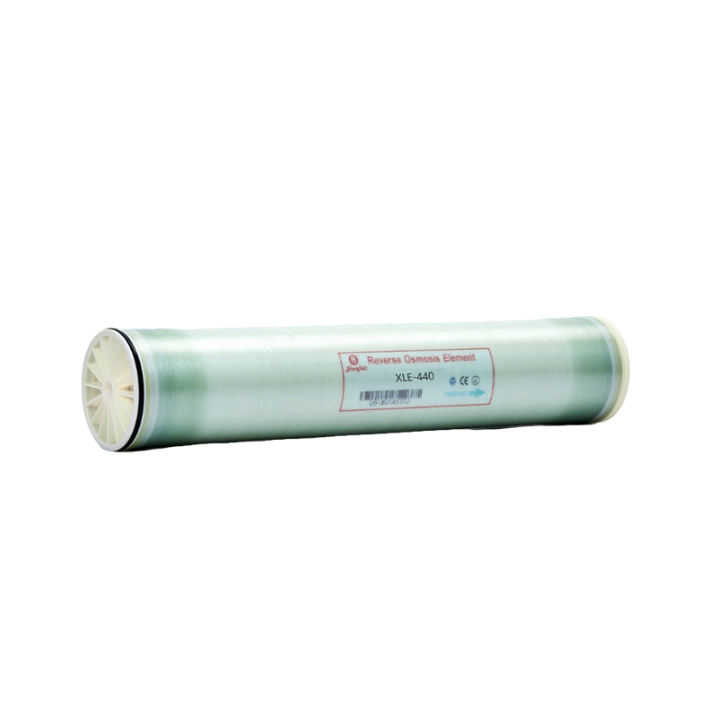
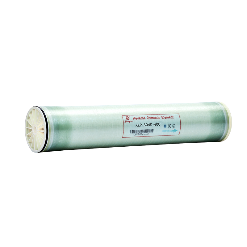
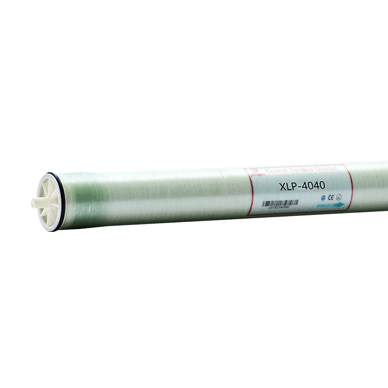
Bangtec's extreme low pressure range covers both compact and full-scale systems. The XLE440 element is an 8-inch element built for high flow per pressure vessel, while the XLP series adds the 4-inch XLP4040 for smaller skids and the 8-inch XLP8040400 for full industrial trains. As a first concrete choice, the XLE440 element is a strong candidate when the feed is clean, the TDS is low, and the plant needs large permeate volume without expanding the vessel count.
| Parameter | Standard BW | ULP | XLP |
|---|---|---|---|
| Typical feed pressure (psi) | 200-250 | 120-150 | 80-100 |
| Stabilized salt rejection | 99.5% | 99.2% | 99.0-99.2% |
| Pump energy vs standard BW | Baseline | 20-25% less | 30-35% less |
| Suitable feed TDS (ppm) | 500-8,000 | 500-3,000 | Below 2,000 |
The table compares typical class behavior, not a specific datasheet. Actual values shift with feed temperature, recovery, and element model, so verify the test data for the exact element you plan to install.
The reason to choose an XLP element is almost always energy cost. Pump power for a given flow is roughly proportional to discharge pressure, so reducing the pressure from 200 psi to 100 psi cuts the hydraulic load on the pump roughly in half.
A concrete example: a 50 gpm industrial RO train operating 8,000 hours per year. Reducing feed pressure from 200 psi to 100 psi saves roughly 20,000 to 25,000 kWh per year. The saving does not stop at the pump. At lower pressure, the whole high-pressure loop, including the pump, motor, VFD load, and piping stress, sees less wear and a lower peak demand charge.
The percentage depends on the starting pressure. Plants already running ULP elements will see a smaller gain; plants running standard BW elements at 200 psi or more will see the full 30 to 35 percent.
XLP elements are designed for clean feed water with relatively low dissolved solids. The strongest fits are:
For full-scale systems, the XLP8040400 element is the practical choice in standard 8-inch vessels. The same element also works in retrofits where a plant wants to keep its existing vessel layout and simply replace the elements.
What XLP is not for: seawater, high-salinity brackish water above roughly 3,000 ppm, or streams with heavy organic fouling. For those conditions, a seawater element, a standard BW element, or a fouling-resistant series is the better starting point.
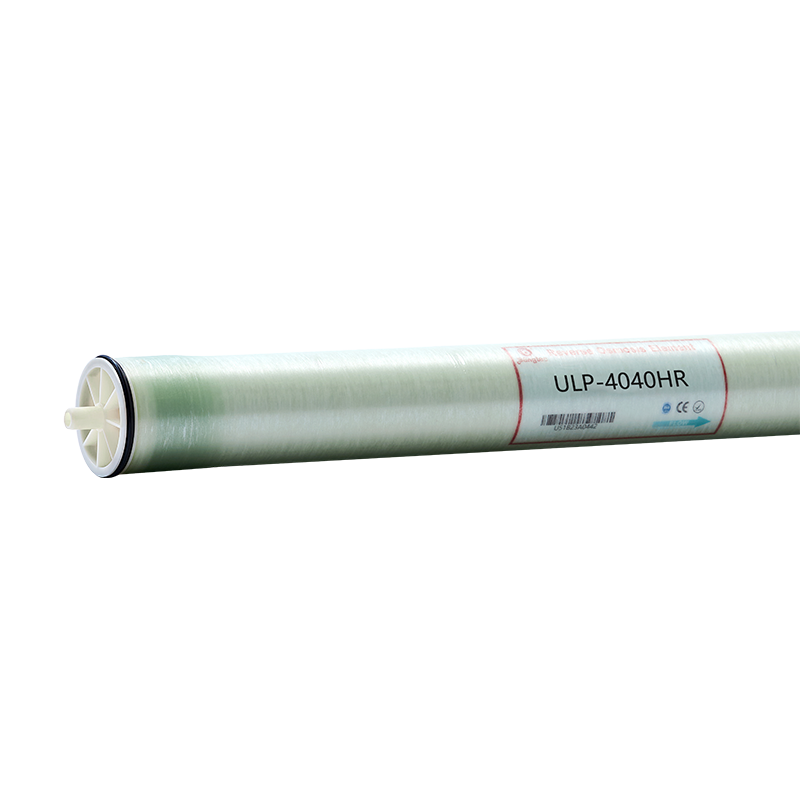
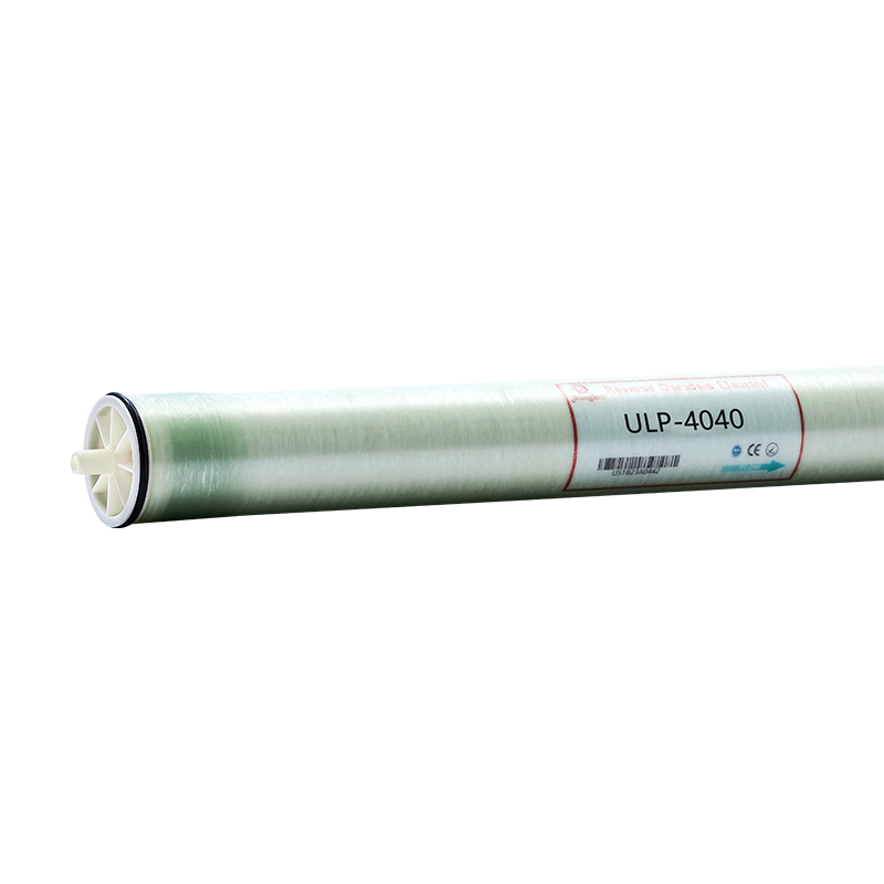
One of the practical advantages of XLP elements is that they use standard 4040 and 8040 housings. There is no need for a new pressure vessel, new piping, or a new membrane skid. The XLP4040 element fits existing 4-inch vessels and is a straightforward choice for mid-size industrial systems.
Three design checks matter before you make the swap:
Most retrofits happen during a scheduled membrane change-out. The labor is the same, the housings are the same, and the only real work is resetting the pump's operating parameters.
For many projects, a catalog element is enough. For others, the difference between a good system and an excellent one comes from tailoring the membrane to the feed water, the recovery target, and the operating schedule. Bangtec manufactures its own membranes on an automated production line with an annual capacity of 15 million square meters, and the R&D team has backgrounds from GE and the Chinese Academy of Sciences. That combination supports custom work beyond simple label changes.
Typical customization requests include a custom active area and element length to hit a specific recovery target, feed spacer choices matched to colloidal or biofouling risk, adjusted permeate flow and rejection targets, and OEM labeling or packaging for equipment manufacturers. For large projects, batch-level consistency matters more than a single datasheet tweak, and a manufacturer that controls the full casting, coating, and winding process can deliver that consistency.
If you are evaluating a custom XLP element for your plant, a useful next step is to look at the automated production facility and understand how the membrane is made, from polyamide casting to final element winding.
The right pressure class depends mainly on feed TDS and the rejection you need. A practical shortcut:
These are starting points, not rules. The final decision should be based on a projection of annual operating cost, not on the datasheet alone.
A custom extreme low pressure RO membrane is a mature, low-risk way to cut operating cost when your feed water is clean and below roughly 2,000 ppm TDS. You keep the same vessels, swap in purpose-built XLP elements, and reduce feed pressure to around 100 psi while maintaining rejection above 99 percent. The pump energy saving of 30 to 35 percent pays back quickly, and for plants already planning a membrane replacement, the extra work is minimal.
Before making the change, verify your feed TDS, review your pump curve, and ask your membrane supplier for test data under conditions that match your site. For more background on membrane selection and application, the industry application notes are a practical reference.
Popular Products

+86-513 8659 8187
+86-189 6299 3952
No.28 Wenjing Road, Nangtong High-tech Industrial Development Zone, Jiangsu Province, China


 EN
EN  عربى
عربى