
Content
Two numbers decide whether an integrated RO + UV ultrapure water system performs: the permeate quality the RO stage can hold through your worst feed week of the year, and the UV dose the lamp still delivers on its last day of service. Neither number usually appears in the quotation.
Get both right and the rest of the train behaves. Polishing resin lasts its expected cycle, resistivity sits at 18.2 MΩ·cm instead of drifting between 17 and 18, and TOC stays under the limit without extra sanitisation. Get them wrong and you spend the first year chasing symptoms: resistivity that dips after every lamp change, bacteria counts that return three weeks after a hot water sanitisation, and resin that exhausts in half the predicted time.
The sections below work through those decisions in the order they actually constrain each other.
An integrated system means one skid, one controller and one validation package. It does not mean one process step. A typical ultrapure train running from tap or process water looks like this:
The stages interact, which is why integration earns its place. A 185 nm lamp converts organic carbon into CO2 and traces of organic acids, and those species must be removed by ion exchange downstream or conductivity rises. A 254 nm lamp placed after the polishing resin acts as a re-contamination barrier; the same lamp placed before the resin only adds oxidant load to it.
Illustrative specific energy demand in kWh per cubic metre for three ultrapure configurations. Confirm against your own pump curves and load profile.
Most specification errors come from treating UV as a single component with a single dose. The two wavelengths used in ultrapure water do different jobs and belong in different positions in the train.
| Stage | Main function | Typical placement | Typical dose | Watch out for |
|---|---|---|---|---|
| 185 nm UV | TOC oxidation | Upstream of polishing resin or EDI | 100 to 200 mJ/cm2, set by the TOC target | Produces CO2 and organic acids that need downstream ion removal |
| 254 nm UV | Microbial control | Downstream of polishing resin, in the loop | 30 mJ/cm2 or more at end of lamp life | Placed too early it protects nothing that reaches the point of use |
Delivered dose is the number that matters. Lamp output falls across service life, and the quartz sleeve fouls with iron, hardness and organics carried over from pretreatment. Design at end-of-life output with a fouling allowance, and trigger replacement on measured output rather than on a calendar.
Illustrative relative UV output against operating hours, comparing a clean quartz sleeve with one fouling at a steady rate.
The RO stage is where the design is either fixed or broken, because membrane area cannot be adjusted later without rebuilding the skid. Five feed parameters decide most of it:
The general logic, from feed analysis to element family and array configuration, is set out in this note on RO membrane technical principles and selection factors.
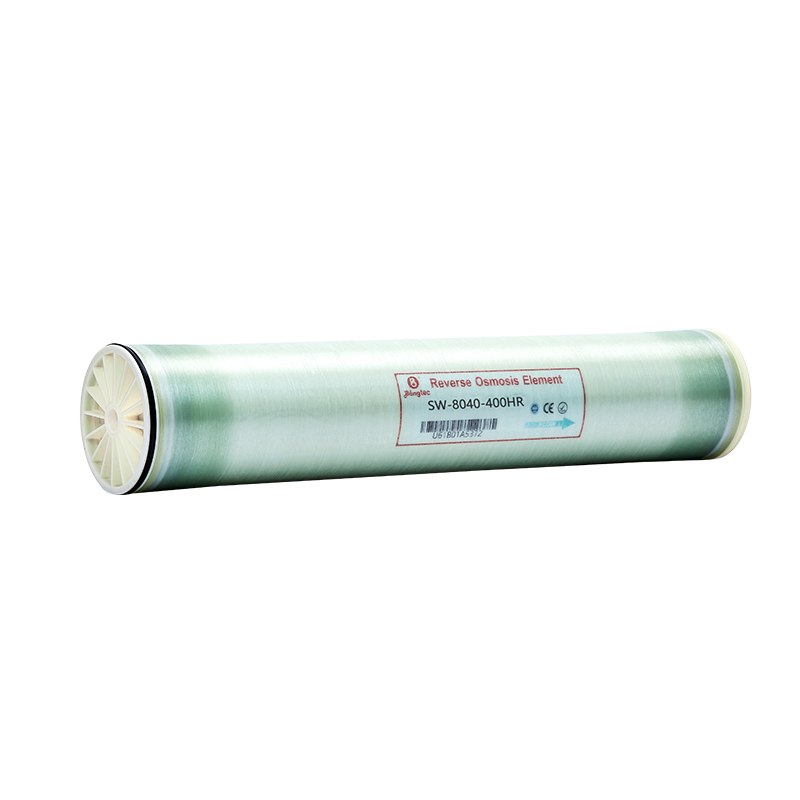
For brackish feed in the 1,000 to 3,000 mg/L range feeding an industrial ultrapure train, an 8-inch brackish water element such as the BW8040400 is a common starting point, with element count driven by flux limits rather than by permeate flow alone.
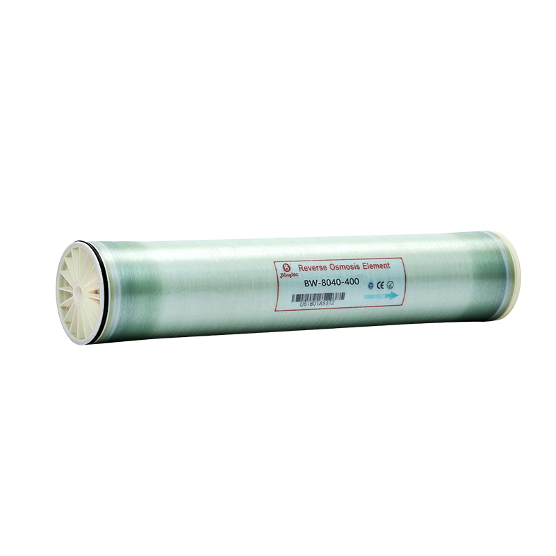 Brackish Water RO Membrane Elements BW-8040-400Brackish Water Ro Membrane Elements BW-8040-400 specializes in desalination treatment for diverse water sources—covering brackish water, surface water, groundwater, an...View Product →
The specification that matters is the one at the point of use, not at the skid outlet. Typical targets for ultrapure water in laboratory and pharmaceutical duty are listed below. Confirm the exact limits against the pharmacopoeia or standard that applies to your product, because they differ between applications.
| Parameter | Typical target | Measurement note |
|---|---|---|
| Resistivity | 18.2 MΩ·cm at 25 °C | Measured inline with temperature compensation |
| TOC | 5 ppb or lower | Some applications accept 10 ppb |
| Bacteria | Below 1 CFU/mL, or below 10 CFU/100 mL | Depends on the method and the sampling point |
| Silica | Below 3 ppb where the limit applies | Driven by the RO stage and by resin performance |
Notice what is missing from that table: there is no target for the RO permeate. The RO stage is a means to an end, so its permeate specification should be derived backwards from the point-of-use limits, with margin left for UV and resin performance between the two.
Two of those failure modes are membrane-side. On feeds with high organics, iron or biological activity, a standard element fouls quickly and the cleaning interval collapses. A fouling-resistant element such as the BW8040400FR, with a surface modified to resist organic and biological attachment, keeps the cleaning interval predictable and shields the UV stage from carryover.
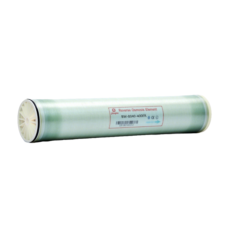 Fouling Resistant RO Membrane Elements BW-8040-400FRThe FR series of fouling-resistant membranes is normally suitable for the treatment of complex water sources with TDS less than 10000 ppm. It is mainly used for the pu...View Product →
Inside an ultrapure train, membrane selection is less about maximum rejection and more about stability. Three considerations dominate.
An ultra-low-pressure element such as the ULP8040400 fits where feed salinity is moderate and energy is a running concern, provided the array is designed at conservative flux so that fouling does not erase the energy gain.
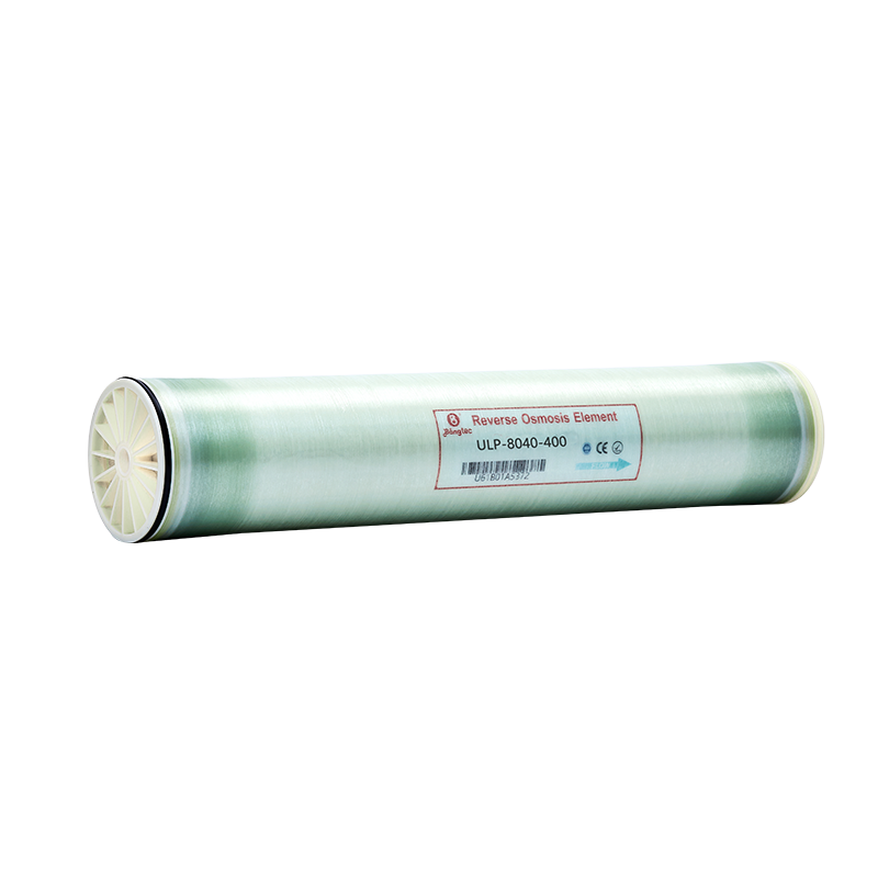 Ultra-low Pressure RO Membrane Elements ULP-8040-400ULP-8040-400 low-pressure desalination reverse osmosis membrane element is a polyamide composite membrane for surface water and groundwater, which has the characterist...View Product →
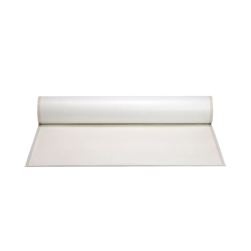
The membrane is only half of the supply question. Element-to-element consistency, membrane sheet availability for special formats, and the ability to reproduce the same specification years later all matter when a plant is being validated. The production line behind the elements is worth reviewing before a long-term supply commitment.
Capital cost is the smaller part of the story. Across ten years, consumables, energy and validation time dominate the cost of ultrapure water. The split below is illustrative; the proportions move with feed quality and with how much of the load the RO stage removes.
Illustrative ten-year operating cost split for a mid-size ultrapure system; substitute your own maintenance records before budgeting.
Planning points that follow from that split: lamp replacement intervals of 8,000 to 12,000 hours are typical for low-pressure lamps, membranes usually run two to four years depending on cleaning frequency, and polishing resin can exhaust in 12 to 24 months when the RO stage passes more organic load than designed. Sizing the RO stage properly is the cheapest way to extend every item on the chart.
Not well. A 185 nm lamp does emit some 254 nm output, but the dose and placement needed for microbial control in a loop differ from those needed for TOC oxidation. Where both limits matter, use two lamps in the positions described in Table 1.
It depends on feed quality. If single-pass permeate stays stable and the EDI or polishing resin can carry the load, a second pass adds cost without adding much. If feed TDS or TOC fluctuates, a second pass is often cheaper than extra polishing capacity and the sanitisation frequency that comes with it.
Replace on measured output, not on a fixed schedule. Low-pressure lamps are typically rated for 8,000 to 12,000 hours, but sleeve fouling can halve effective output well before that. Monitor dose and clean sleeves on the same schedule as membrane cleanings.
No. UV controls microorganisms in the water passing the lamp. Biofilm in dead legs, valve bodies and low-flow branches is out of reach, so periodic sanitisation stays part of the loop design.
An integrated RO + UV ultrapure water system is a chain of decisions that starts with the feed analysis and ends with the point-of-use specification. Fix the finished-water targets first, size the RO stage for the worst feed week rather than the average, place each UV wavelength where its chemistry can be completed downstream, and monitor delivered dose instead of lamp hours. Those four choices determine most of the stability you will see in the first year, and most of the cost you will carry for the next ten.
Popular Products

+86-513 8659 8187
+86-189 6299 3952
No.28 Wenjing Road, Nangtong High-tech Industrial Development Zone, Jiangsu Province, China


 EN
EN  عربى
عربى